Vertical dipole for 20 m by Harper
 
 
The history
For many years as a camper I am on the move by the caravan, and I also wanted always to be preferentially QRV on the
20 m band. Unfortunately, there were not always the suitable trees where I can hang up a wire. A vertical wire at a
Glassfibremast anyway beside the caravan on a foot was not really the ideal solution, because there always were problems
with the mounting. Also, putting up and fixing the mast was always time-consuming.
 
The idea
At the first I had the idea that the caravan shaft is ideal for the mounting of a mast. With it was certain, it must be a vertical
antenna. A resonant dipole would be best of course, because with it there are no problems with the matching. Moreover,
it should be feeded at the lower end, because the 20 m Dipole is two times 5 m long. Then 10 m wire winded at a 10 m
mast, this would have to fit at approx. 9.5 m of length. Therefore approximate another 50 cm remains to clamp the mast.
 
The aerial
So I have taken first of all for the upper part 5 m of wire and for the lower part 5 m of coaxcable RG 58. In the middle only
the center wire
of the coaxcabel is connected to the wire. Then in the feedingpoint I have inserted a coatwaves choke.
The result was satisfactory, but the tuning developed a little bit difficultly. After I then postturned the leaves intensely through
the new "Rothammel", I bumped into the description of the "vertical coaxial dipole by Harper" (see the "Rothammel
Antennenbuch" 12th edition (Krischke) page 453 and the following). Then this had to go at the lower part of the dipole with
coaxcabel with a higher impedance, there is a better compensation of the blind components and the aerial occurs through
it becomes more bandwith. The feed also occurs below in the toe about a coatwave choke. Then it is able about any length
of a coaxcabel go to the Transceiver. I still had several meters of the RG 62 (92 ohms) in my cellar, that was used earlier
on computer networks, and substituted the RG 58 with it. The success was, that now the usable bandwith range became much
bigger. At the moment the dipole exists of 4.70 m of RG 62 and 5.20 wire. The SWR at 14,250 Mc is with 1:1.2,
the usable range within the SWR of 1:3 is approx. 2 Mc, so I have changed nothing more! This "to crooked values" are
closed absolutly with the fact, that the lower part by the ground nearness capacitive as well as by the choke an inductive
influencing finds out.


The development to the 40 m / 15 m aerial
After now this aerial on 20 m worked very well, I considered, how this aerial also for other bands could be of use without
extravagantly adaptation. Then the consideration was the following: the soul of the coaxcable with the upper one wire
together are 10 m, this is immediatly lambda 1/4 of 40 m and 3/4 of 15 m, and therefore resonant! So the coax only is fed
at the center wire . The coatwave choke is substituted with an insulating piece and the inside leader is carried out. There of
course aerials with lambda 1/4 and 3/4 need a counterbalance (earth etc.), this gets the continuing coaxcable at this point
grounded. In this case as a counterbalance the whole caravan works. That the ground is even more efficiently copper-
concealed Epoxy were laid under the props of the caravan, in addition, still in each case 15X30-cm
 
As the next I will try to substitute sometimes for the insulating piece with a coil around thereby to get a resonance on 80 m.
I will report if this aerial also works on 80 m satisfyingly.
 
The implementation

The middle
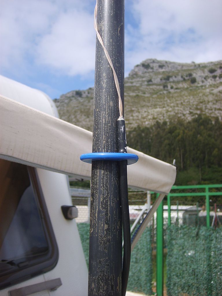
here you can see, how the connection was formed between the upper wire and the lower soul weatherproofly. The blue ring serves for the fixation of the upper end of the RG 62 in the mast, because this is pushed together when not in use on half.
The choke
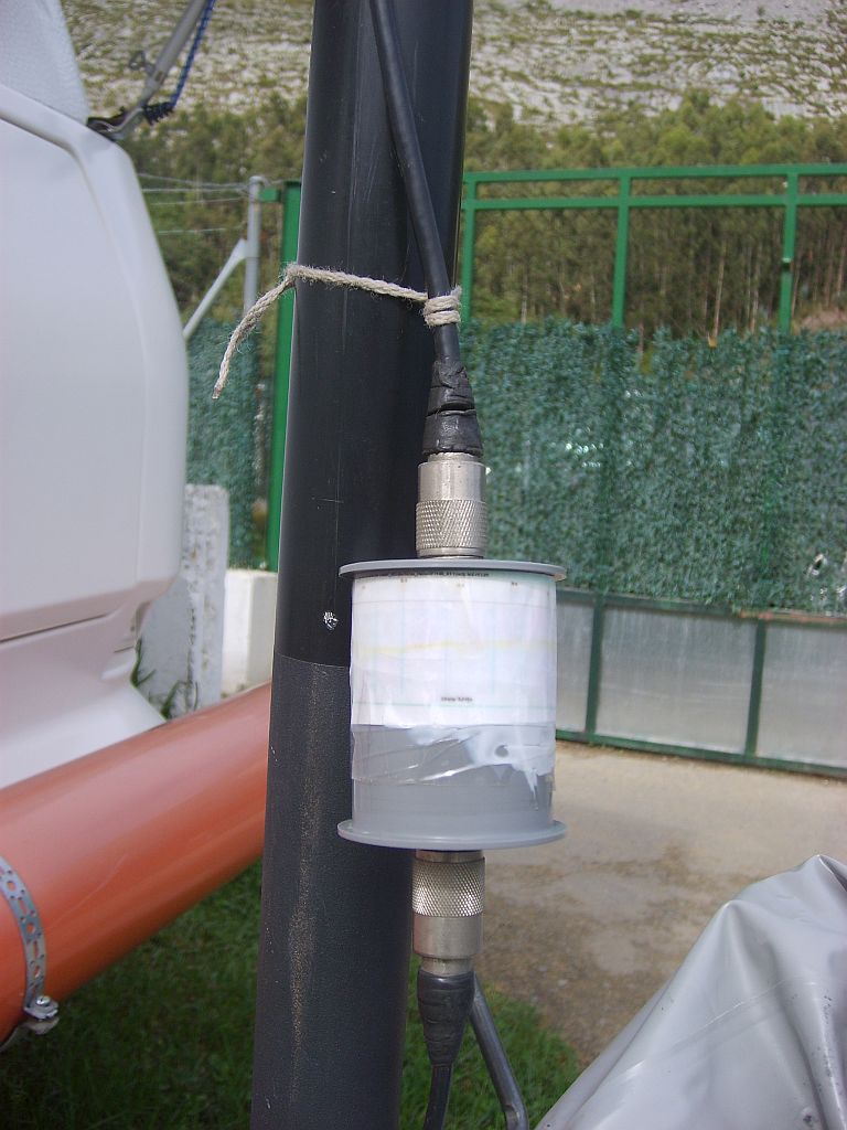
the choke passes of two cores Amidon FT140-43 on each other stuck and 8 - 10 bends coaxial cable RG 188, this is made out of Teflon. The case passes of two caps of the series DN 40 drainpipe.
The interpiece for 40 m
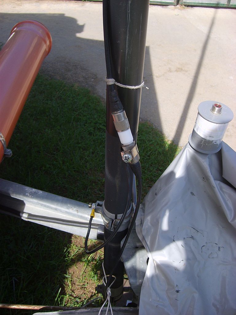
Here you can see the interpiece. It is made out of Teflon, and in the middle a socket is inserted. Also you can see quite clearly how the ground at this point is conected.
The connection
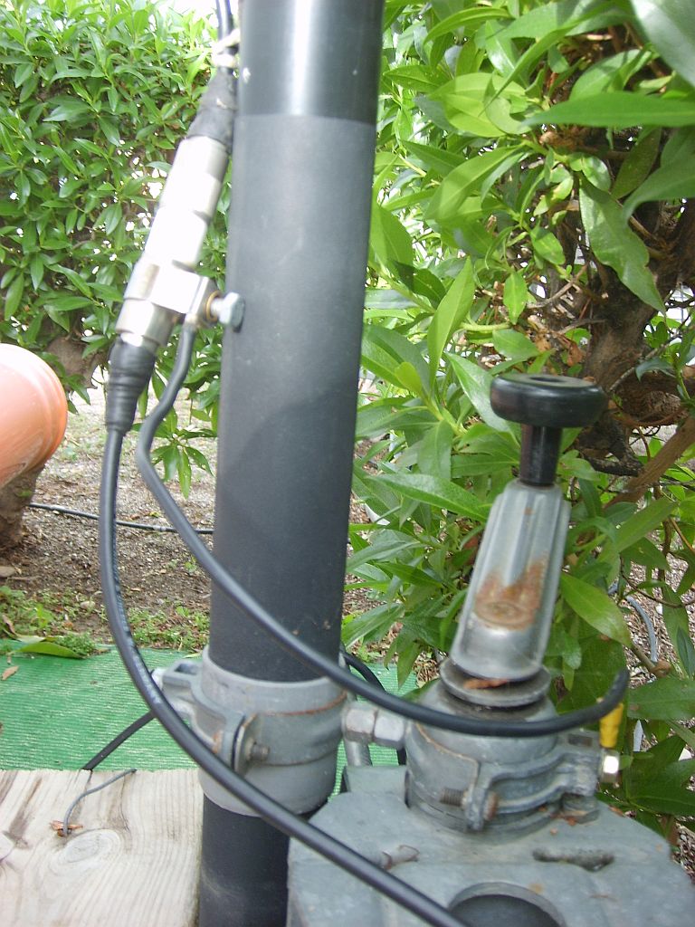
This is made of two times two 2" pipe clamps that each other were screwed together. One side is screwed together in the shaft. The other side is screwed together under intersituation by a piece PVC DN 50 tube with the mast. Then the ground is connected also to this connection.
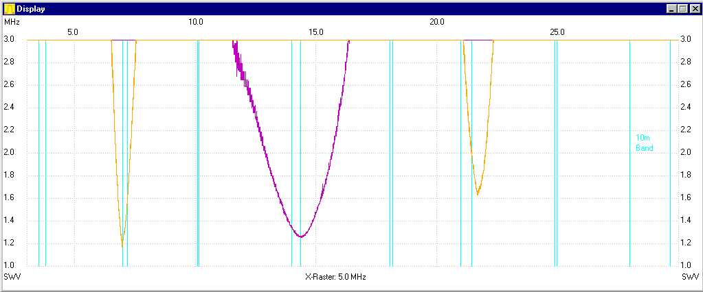
The results
These graphics show the SWR of the 20m band dipole, as well as the SWR of 40m band Marconi aerial. It was measured directly in the toe of the aerial with the FA-network tester. According to local circumstances the curves can move sometimes. Anyway the range is so big at the 20m band, that there will probably be no adaptation problems. Please notice in case of the consideration of the curves that the Y axis shows only one SWR up to three.

I hope that by this implementation some suggestions were present, and now you can see the posibility to
get
QRV at vacation on several bands.

Now have a lot of fun and a lot of successful results while copying.
73 es 55 and gd dx de
Harald DL2MHW